Aerobee
Back in 1998, after building a bunch of kits, I wanted to build a completely scratch rocket and started looking through Peter Alway's Rockets of the World for inspiration. The "Standard Aerobee" rocket is a great looking one and is two-stage, but what really turned me on was the fact that both stages fired at liftoff with the stages remaining together during booster burn.
In order to handle this, I had to design a special interstage. which could handle the heat of a motor firing against it. Of course, it had to look somewhat prototypical as well. This also means that the selection of motors is critical.
After it languished for many years, I got interested in this rocket again in 2014. Since by then I was in the habit of making instructional videos, I decided to make one on Sport Scale Modeling, using this rocket as the subject.
Another new thing for this rocket is my use of TeleMetrum flight computers. These incorporate GPS coordinates and telemetry into the flight computer itself, providing a single unit telemetering all relevant data. Never one to do things by halves, I'm using two in this rocket.
The Pictures
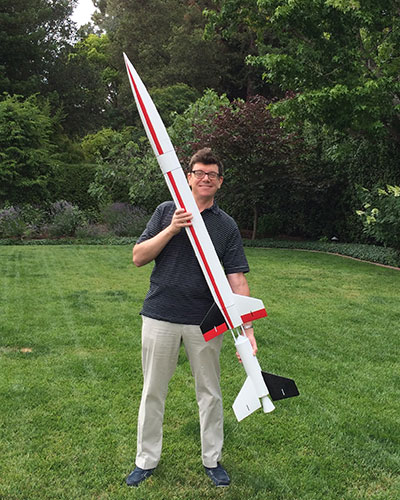
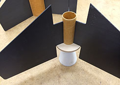
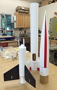
And the first proud picture of me holding the newly completed rocket (July 1st 2014).
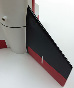
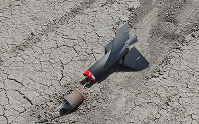
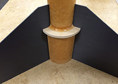
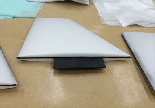
And I couldn't resist a close-up of the black sustainer fin, nicely showing the profile (see the fin section below).
Aeronaut 2014
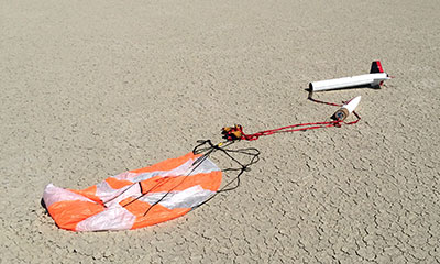
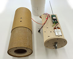
The rocket was mostly prepped on Friday, and then flew on Saturday, August 2nd, 2014 at the AERO-PAC Aeronaut launch. Here is the sustainer on the table ready to go, with the booster in the ground in front.
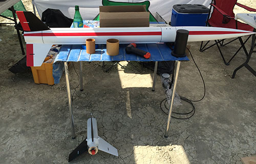
I flew it on an H195 to a J90 (see Motor Selection below). This was a good pair of motors for the desired flight profile, except that the J90 took too long to come up to pressure (even with one of Tony's super igniters).
So, it staged rather than both motors firing at once.
Despite this, it was a beautiful flight and the TeleMetrum and R-DAS both recorded the sustainer
achieving about 4500' altitude.
The booster never achieved enough altitude for the TeleMetrum to detect an actual flight and so
it lawn-darted in very near the pads.
Luckily, the interstage was so tough that there was no damage.
This video shows the flight from below.
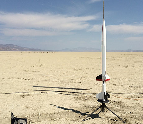
Here it is on the pad, out in the ever-beautiful Black Rock desert. It was nice that it's still just a "complex J", so I could fly it off the middle rack.
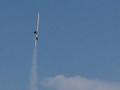
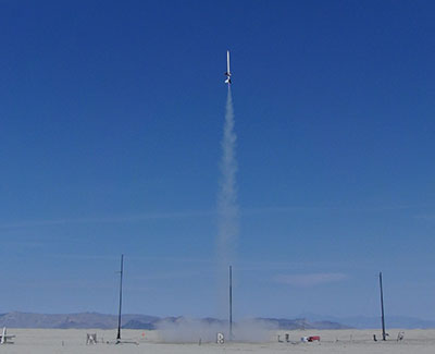
Here's a decent picture in-flight, still on the booster motor. (The sustainer motor was supposed to be burning also by this time, but took too long to come up to pressure.)
This was my first flight of a TeleMetrum flight computer. Actually, I few two: one in the sustainer (backed up with an R-DAS) and one in the booster. The one in the sustainer worked just fine, but the one in the booster got confused.
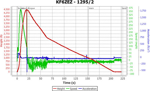
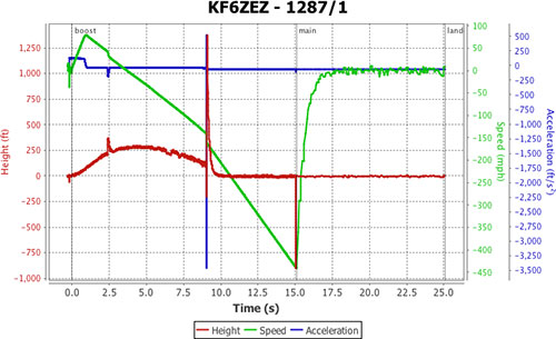
Above is the data from the sustainer TeleMetrum and below from the booster unit.
For comparison, below is data from the R-DAS (in the sustainer).
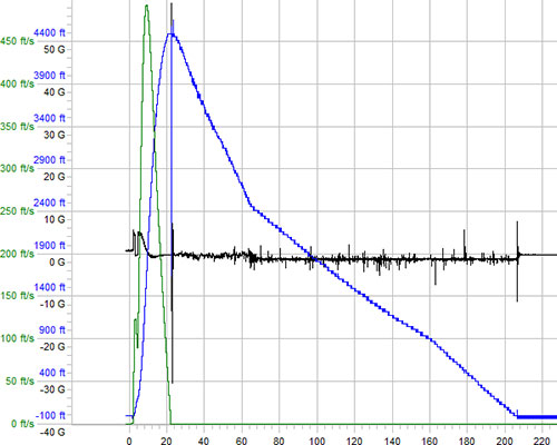
In the end, I'm satisfied with the performance of the TeleMetrum; I received GPS tracking all through the flight. Even though the telemetered flight data seems to have been corrupted at one point, I still got landing coordinates and the downloaded data seems fine.
However, the booster unit performed very strangely. At first, I thought it was due to the flight being low and/or the acceleration being low, but if you look at the altitude data, you'll see that it's implausible. Also, the unit fired the ejection charge some time after it lawn-darted in.
XPRS 2014
After the failure of the TeleMetrum in the booster, I decided to keep it simple and use motor ejection on the H195. I also decided to use the newly reissued K250 in the sustainer.
I like the original K250 better; it truly was a single-use motor, coming ready-to-fly in a fiberglass case. The new version requires using your own closures, which means there is clean-up after use.
In hopes of getting the sustainer up to pressure faster, I reduced the staging delay to 0s (fire the sustainer at lift-off). As it turned out, this still wasn't fast enough and the sustainer didn't light until after booster burn-out.
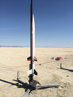
This time I had to go out to the far pads (complex K distance). Above you can see the rocket on the 750' rack.
Above you can see the rocket just before booster burn-out; still together and no sustainer ignition yet.
Once again the booster didn't go high enough for recovery, even though I shortened the delay as much as possible. Good thing the forward end is tough and not falling very far.
An the sustainer was recovered three miles down range (single deployment). This time the sustainer reached 13,200' according to the R-DAS and 12,961' according to the TeleMetrum (max velocity of 1090 and 1106ft/s respectively).
I've also posted a YouTube video of both flights.
The Design
See Rockets of the World, pages 95-102 for detailed plans and a discussion of the prototype rocket. If you don't have this book, you're missing out on the most valuable prototype resource in rocketry. You can order it from ARA Press.
|
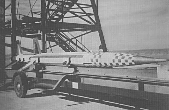 Above:
Aerobee USAF-2 displays its paint job before launch.
See larger picture.
Above:
Aerobee USAF-2 displays its paint job before launch.
See larger picture.
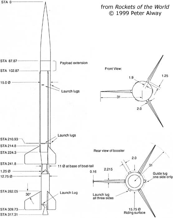
Left: Peter Alway's excellent plans from Rockets of the World, page 96. See larger drawing. |
|
The first thing to do with a scale rocket is to pick a scale factor, which determines the size, or pick the size which determines the scale factor. It's easiest to choose a size to fit available tubing, so I chose a 4" sustainer O.D. so that I could use standard 3.9" tubing.
This set the scale at 25% (roughly). Using that scale factor, standard 3" tubing matches the booster reasonably well (close enough for sport scale anyway). See the overall drawing for model plans.
To preserve a good motor selection, I wanted the upper stage to use a 54mm motor mount. Because the struts on the interstage need to go around the motor mount, a minimum practical diameter for the interstage is about 3". (The interstage is at the bottom of a boat tail and the body of the sustainer is actually somewhat wider.)
In order to get anything like the nozzle profile that forms such a prominent feature of the booster, I was going to have to use a 29mm MMT. That meant that this rocket needs to be light enough to be flown on a 29mm motor!
The Interstage
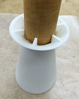
The interstage is two parts, the upper and lower. To be true to the prototype, the interstage is open and the sustainer motor fires at the same time as the booster motor. This means that the interstage and booster airframe need to withstand high temperatures.
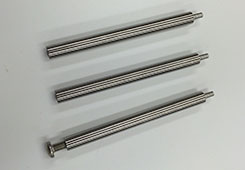
In order for this to work, I need to use metal or ceramic parts for the lower interstage. The good news is that they are only subject to this temperature for a couple of seconds (until the booster burns out and the stages separate). Metal is better for strength, so the struts would be stainless steel. The cone has no structural purpose, so can be ceramic.
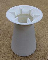
The upper interstage houses the sustainer motor mount (single 54mm) and fits into a 3" airframe tube. The sustainer boat tail starts at the lip of the upper interstage and grows out to the sustainer airframe width of 4" O.D. See the interstage drawing for details.
The lower interstage fits into the top of the booster airframe and forms the cap of the booster. This section has a built-in shoulder which slips into the booster body tube. For booster recovery, the cap pops off just like a normal rocket's nose cone. For simplicity and space considerations, the booster uses motor ejection to eject the 'chute
Motor Selection
The other challenge for properly staging this rocket is to make sure the booster motor fires with enough thrust to lift it, and the upper stage faster than the sustainer motor is lifting just the sustainer. Since the sustainer is being lifted in both cases, the booster motor needs to apply more thrust, minus the booster weight, than the sustainer motor produces throughout its burn. In addition, I want the sustainer to be stable by itself in case its motor ignites and the booster motor does not.
For prototypical operation, the booster motor should be a short burn and the sustainer a long burn. This also fits in well with the thrust requirements. The sustainer uses a 54mm motor mount, so there is a good selection of long-burn motors.
The booster body is a 3" tube, but the MMT is only 29mm, which limits the motor selection a lot. Also, the maximim length is limited to about 15" so there is room for recovery (a little extra length is gained from the 3½" nozzle). The final weight (after painting) turned out to be 2.18# (1Kg).
For more information on motor selection in general, see the INFOcentral Motor Selection article.
For the first flight, I decided to use an AeroTech H195 in the booster and an AT J90 in the sustainer. This sims to about 7000' and stays under Mach 1.
Construction
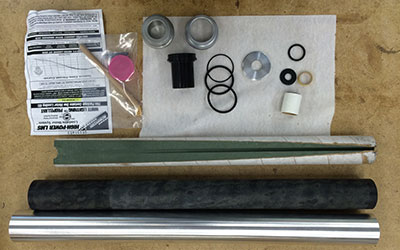
The first task was to figure out exactly what parts I would be using. I had some 3.9" carbon fiber airframe left over from a prior project, which I considered using, but it turned out to be heavier than phenolic. In order to keep things as light as possible, I decided to keep it simple and use phenolic for the airframe and ¼" plywood for bulkheads and centering rings.
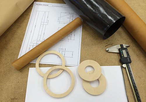
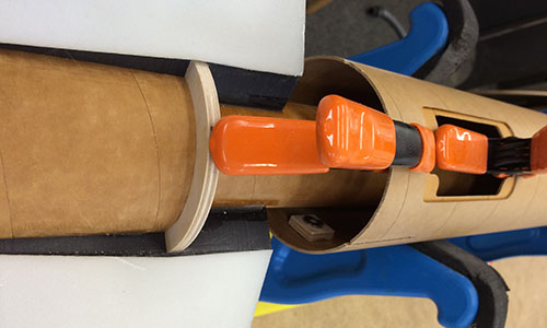
Above you can see the tubing and some test centering rings to get the ID/OD perfect before the final versions were cut. (The interestage has a lot of complexity so I wanted everything to fit perfectly.)
Actual construction began on March 15, 2014 when I cut and fiberglassed the booster airframe. On Sunday, I finalized the internal structure and cut out the various plywood centering rings.
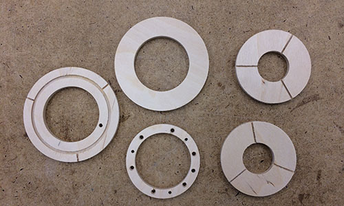
Above you can see the centering rings for the booster and sustainer. The smaller diameter booster CRs (on the right) are slotted for the fin cores and the sustainer rings (left and center) have to accomodate three different tubes, plus the interstage struts and motor retention.
Booster
The booster is dominated by the huge nozzle at the aft and the interstage base and cone forward. Between them, construction is relatively traditional, with a 29mm MMT in a 3" airframe. Motor ejection is possible, but I decided to build a small electronics bay into the coupler for the interstage base anyway.
 |
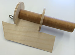 |
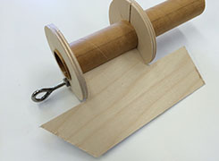
Above you can see two views of a test-fit of the fin cores, which slots into both centering rings. Note that this plywood piece is a stand-in for the actual core, which will be carbon fiber plate.
 |
 |
 |
Of course, the really special detail is the huge aft nozzle. I had this part made using a 3D printer by Shapeways and it came out quite nicely. The surface was a bit rough, but a little filling and sanding should make it perfect. Note in the center photo how I used threaded inserts to provide anchors for motor retention.
Finally, the aft end of the nozzle was capped off with a thin aluminum thrust plate.
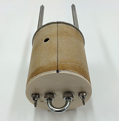
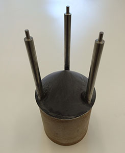
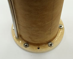
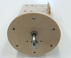
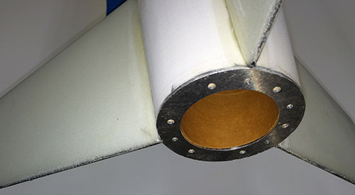
Then it was on to the forward end of the booster to build the base of the interstage. The most prominent feature is the aluminum plate and three stainless steel struts, but they rest on top of a plywood ring that forms the forward end of a small electronics bay.
 |
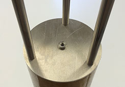 |
This plate rests on top of a plywood ring that forms the forward end of a small electronics bay and the struts bolt to the plywood ring and through the aluminum plate. The pins on the ends socket into matching holes in the base of the sustainer.
 |
 |
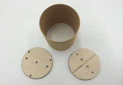
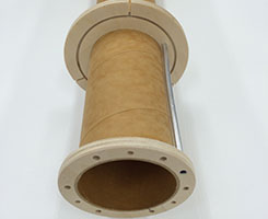
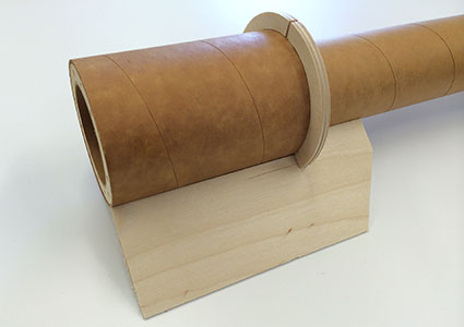
Above are the parts and a side view of the completed bay built into a coupler that slides into the forward end of the booster airframe tube.
 |
 |
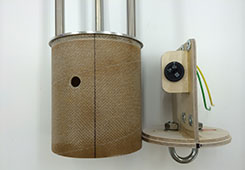
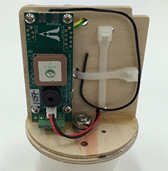
Above you can see the AltusMetrum mounted onto this tiny plate, with the unit on the front side and the battery on the back. On the right, you can see how it slides into the coupler, completing the booster half of the interstage.
Once the forward end was complete, it was back to the aft end to complete the fin can. (See the section below on making the fins.)
The three fin tabs fit into slots in the two centering rings (see above), forming the fin can around the 29mm MMT. Then it was just a matter of bonding everything into a solid unit.
The booster body was completed by bonding the fin can into the short airframe section. Once the external fillets were applied, the only task remaining was the rail guide.
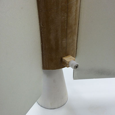
Since the booster is smaller diameter than the sustainer, the rail button had to be built out. The prototype actually had rail guides on all three sides, so I went ahead and added that detail to the booster. The side shown has the rail button and the other two sides have blocks without the button.
The final part is the aft end of the interstage, which acts as the forward cap of the booster. The last piece I fabricated was the cone itself. This has to survive the exhaust from the sustainer motor directly blasting down onto it, for at least a brief time, which meant that I would have to use a ceramic material. Cotronics makes a machinable ceramic (Rescor™ 902), which I was able to machine on the ShopBot.
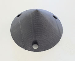 |
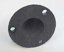 |
The pictures above show a top view of the cone, as well as a bottom view. I decided to hollow out the bottom to reduce weight. Overall, it came out OK. There were some strange machining artifacts and the ceramic was a bit brittle for the fine edges, but I was able to fill/sand these out.
I bonded the ceramic to the aluminum plate and stainless steel struts using Cotronics high-temperature epoxy (4700). This required an elevated-temperature cure, but this part is so small I was able to use a toaster oven.
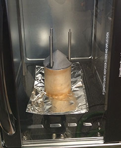 |
 |
The ceramic cone cracked slightly during curing, so even the relatively low temperature must have caused it to expand or contract slightly. We'll see how it survives in flight.
Sustainer
The aft end of the sustainer is defined by the interstage, while the forward end is pretty standard. I didn't have room for dual-deployment on this rocket, so I kept things simple. The electronics bay is at the forward end of the airframe, just below the nose, which allows the TeleMetrum antenna to stick up into the nose cavity.
 |
 |
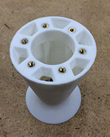
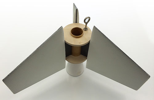
Above are two views of the aft end of the sustainer, built around the 54mm motor mount tube. There are three holes for the interstage posts to socket into, six #6 T-nuts for motor retention and one tube to pipe the igniter from the staging electronics bay between the fins.
And with the 3" tube on over the aft core, a test-fit of the fin core, which slots into the forward centering ring and over the aft one. Note that this plywood piece is a stand-in for the actual fin core, which will be carbon fiber plate.
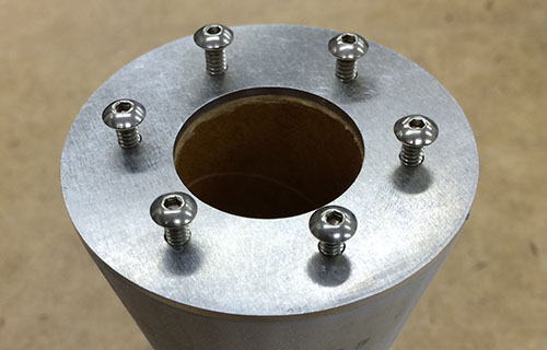
The final piece of the sustainer end of the interstage was an aluminum plate to cap everything off.
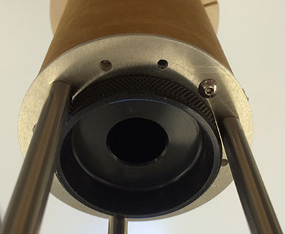
The pins on the struts socket into three of the holes. Six of the holes are available for motor retention (see the 54mm motor mounted into the MMT). And one is the end of the tube connecting to the staging electronics bay.
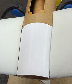
Once the interstage was complete, it was time to move on to the forward end of the sustainer. I decided to put the bay at the front end, right below the plastic nose cone. The bottom of this section of airframe corresponds to a paint color change in the prototype (there is a white section above where the ribs end).
 |
 |
The electronics bay slides in from the forward end and screws into a ring mounted inside the coupler to the main airframe. The nose cone itself acts as the cap to the bay, providing plenty of space for the TeleMetrum antenna. (The TeleMetrum is mounted in the picture above, and you can see the space for the R-DAS on the left side of the sled.)
Once the forward end was done, it was time to go back and finish up the aft end. This is a very interesting section, not only because it contains the forward half of the interstage, but also because it has a tail cone that the compound curved fins need to match. (See the next section on making the fins.)
Above you can see the aft end of the sustainer, with the fin can partly inserted as the mounting plate for the hatch cover is being installed. See my article on making a routed airframe hatch for details.
A prominent detail of the sustainer is the tail cone, made in three pieces of 3D printed plastic that fit between the fins. (Like the booster nozzle, these were made using Shapeways.)
Once the plastic transition pieces were bonded in place, the aft end was finished off with an aluminum plate and external fillets applied. This aluminum plate is important for precise registration of the interstage struts and to provide a solid aft end.
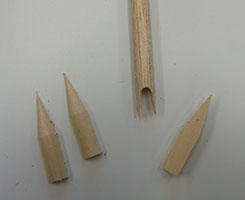
The final detail for the sustainer was the three conduits that run from the fins up to the forward end of the main airframe. Once again, these were cut out on the CNC router, the tips from basswood (for strength) and the length from balsa (for light weight).
 |
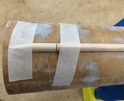 |
Above you can see all three tips and one of the bodies of the conduit detail. (The notch in the body is to fit around the forward end of the fin.) The tips were then tacked to the bodies with CyA and bonded to the airframe with epoxy and held in place with masking tape.
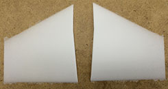
Fins
The Aerobee fins are interesting also. They have a rounded cross-section from forward to aft as well as tapering from root to tip (as best as I can tell from photos and the drawings in RotW). I decided to use 1/16" carbon plate cores and build up the profile with foam, all cut on the CNC router.
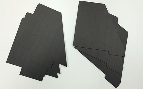
Above you can see the six cores cut out of carbon plate for the three booster and three sustainer fins. These were a straight-forward CNC routing cut-out operation, although it was the first time I'd cut carbon plate this way. Below you can see the fins test-fit into the rings cut in the sustainer (left) and booster (right).
 |
 |
The fin profiles were another new adventure for me, using the CNC router to cut a curved surface shape. The first challenge was learning how to draw the objects in 3D. As with the 3D printed parts, I used Rhino because they had a free Mac download.
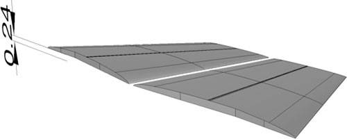
Above is a perspective view of the two faces of a single sustainer fin profile. Once the parts were drawn, I used Vectric PartWorks 3D as the CAM system. This program is very straight-forward to use, just a wizard you walking through the process of laying out the shape in the material block and producing the rough-out and finishing tool paths.
 |
 |
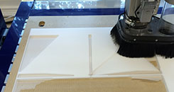
Above left you can see the ShopBot working on the profiles. Both pieces have been roughed-out, and it's slowly working on the profile on the right side. Above right are the finished profile halves for one sustainer fin.
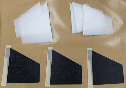
The next step was to bond the profiles onto the core epoxy. In the picture above, you can see the cores and profiles laid out, ready to go.
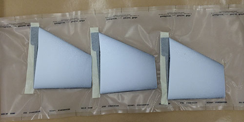
A light coat of epoxy was applied to the profiles and they were tacked in place with CyA. Excess was trimmed off with a knife and the the fins went into the vacuum bag to cure. Finally, a layer of 4oz. fiberglass was vacuum bagged to the surface to create a hard skin.
The booster fins were basically the same, except for a less complex profile and with the tab in the center.
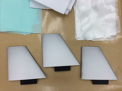
Above you can see a top view of the booster fins after bonding the profiles to the cores and getting ready to laminate fiberglass onto the surface. Below you can see a close-up of how the profile forms the compound curves on top of the core.
Once the fins were laminated, they were bonded into assemblies that slide into the sustainer and booster airframes.
Finishing
I decided to finish mine as USAF #1 (first round fired) and using rattle cans. In order to keep things as light as possible, I went for a "good from far, but far from good" level of preparation: 1 iteration of prime/fill/sand before the color.
I still wanted it to look like its prototype, at least from afar, so I painted the fins and body appropriately and added the white stripe. The number 1 (roman numberal I) on the fins was done using vinyl decals from Sticker Shock 23.
I didn't fully fill the pores in the fiberglass lamination on the booster fins, but just shot them with color (white and black). However, the sustainer fins needed more careful preparation since they were two colors (white or black body with a red stripe along the aft) and I needed a smooth surface to get a sharp paint line. Rather than endless coats of spray primer, I brushed on Kilz primer which did it in just two coats. Yes, I used a paintbrush on this rocket!
Still, it's always pleasing when painting is finished. Even if there are small blemishes, it doesn't really matter on the finished product.
Historical Info
Text from Rockets of the World. (The Aerobee article starts on page 95 of the third edition.) I have also scanned in Peter Alway's drawing for reference.
Standard Aerobee
Although the V-2 overshadowed the Wac Corporal in the post-war years, the V-2 was hardly an ideal sounding rocket. Not only were they in short supply, but the captured missiles had been built in the desperate last days of WW II Germany, often using inferior materials. As the rockets aged, their reliability became worse. Even the one ton payload capacity of the V-2 was a mixed blessing. Scientists were tempted, and even encouraged, to load too many experiments onto each flight, introducing complexity that sometimes led to disaster. It was often impossible to get the various bits of complex equipment of several experimenters to work simultaneously on the day of the launch. In one case, a pressurized compartment for a rhesus monkey had to be built with such an irregular shape to fit around the other experiments that it could not be made air-tight. If the weight of a payload was short of a ton, extra lead ballast had to be added to guarantee stability of the missile. Late in 1945, the Applied Physics Laboratory of Johns Hopkins University (APL) assigned to James Van Allen the task of surveying the nation's sounding rocket needs. In 1946 he reached his conclusion: the American scientific community needed a new small rocket, adapted from the Wac Corporal.
The new rocket, built by Aerojet, and drawing from the Navy's Bumblebee missile project, would be called the Aerobee. This enlarged descendant of the Wac Corporal was tiny in comparison to the V-2, but it was to prove much more useful. The Aerobee was powered by a furfuryl alcohol/aniline mix burning with red fuming nitric acid, as was the Wac Corporal. Like the Wac Corporal, it was assisted by a small solid booster at liftoff. The Aerobee and its booster were stabilized only by fins, which also added a spin to reduce dispersion (error) in its trajectory. Because the Aerobee accelerated slowly, a launch tower was required for the first ninety feet of flight until the fins could work effectively. A 140-foot (53 m) launch tower was constructed at White Sands for the Aerobee in 1947. This was later joined by towers at Fort Churchill, Manitoba and Wallops Island, Virginia. Several Aerobees were fired from a shipboard tower from the USS Norton Sound.
The Aerobee could loft a 150 pound (68 kg) payload to an altitude of over 82 miles (130 km). The original (Standard) Aerobee design first flew September 25,1947, and remained in use for over ten years, lofting scientific payloads for the Air Force, the Navy, and the Army Signal Corps. Near the end of its life, an improved version, sometimes called the Interim Aerobee Hi, was developed, with increased thrust and lengthened propellant tanks.
One of the chief advantages of the Aerobee's small size was portability. Within two years of its introduction, the Aerobee set out to the Pacific Ocean for the first shipboard sounding rocket launches on the earth's magnetic equator. Aerobee A-10, sponsored by the Applied Physics Laboratory, was loaded into a short launching tower aboard the USS Norton Sound (AV-11) on March 10, 1949. It carried an array of Geiger counter telescopes to determine the direction from which cosmic rays were arriving, as well as an unshielded counter to measure the overall cosmic ray flux. If the cosmic ray direction was affected by the Earth's magnetic field, scientists would know that they consisted of charged particles. It also carried a magnetometer. The rocket left the deck of the ship on a normal trajectory, verifying the practicality of the shipboard launch technique. It reached a peak altitude of 65 miles (103 km), relaying back good cosmic ray and magnetometer data. Later analysis confirmed that bare, positively charged hydrogen nuclei (protons) dominated the cosmic rays.
This was the first of a series of launches every few days. One of these, A-12, was set to boost a similar set of instruments a week later. The Aerobee with its booster was loaded into the tower and its tanks were filled. But ten minutes before the set launch time, there was a leak in a tank pressurizing valve. This forced the hypergolic propellants into the combustion chamber, and the sustainer took to the air unboosted, reaching an altitude of 19 miles (30 km).
Aside from this mishap, the sea voyage was a success, providing good cosmic ray data from several flights, and incidentally allowing James Van Allen and colleagues an opportunity after hours to dream up the Rockoon scheme, which was to be so successful in the future. The Air Force began flying Aerobees in 1949. Their first launch was to test parachute recovery of the payload, which contained aerial cameras and photographic emulsions to study solar X-rays. In addition, the aerodynamics of the Aerobee would be studied. Aerobee USAF-I lifted from White Sands at 3:20 PM on Dec. 2. As the rocket reached its apogee at 60 miles (100 km), the nose separated and the parachute opened. Six months later, the nose was found, attached to a shredded parachute. The aerial photos and x-ray emulsions were useless. The red and white checked nose of the second Air Force Aerobee carried a University of Michigan payload containing thermionic ionization gauges and two alphatron gauges. The nose cone was modified with a conical extension topped by an air inlet. At 10:10 AM, on Dec. 15, 1949, Aerobee USAF-2's booster ignited. The rocket flew from the tower and exploded. The nose cone was found about 1000 feet (300 m) from the tower.
The Aerobee was a useful instrument for examining the fundamental gas properties of the upper atmosphere: pressure, density, mean molecular weight (composition), and temperature. Temperature was of special interest. but it could be determined if one knew the other properties. The relatively cheap Aerobee was ideal for taking temperature measurements over a wide range of places and times. But a simple, inexpensive payload was also needed. The method invented by the University of Michigan's High Altitude Engineering Laboratory, and paid for by the US Army Signal Corps, was a relative of the model rocketeer's ping pong ball duration: the falling sphere method.
Air resistance is dependent on the shape of an object. its speed, and air density. If one knows speed, drag forcer size and shape, one can find density. A spherical body is convenient because its shape is independent of its orientation. So the trick was to send a sphere through the tenuous upper atmosphere and carefully follow its trajectocy, then subtract the effects of gravity. Any remaiaing velocity change would be deceleration due to aerodynamic drag. Limitations on the accuracy of the radar tracking system at White Sands meant that drag effects on a 15" (38 cm) sphere (the diameter of the Aerobee) would be too small to measure. In addition, the sphere had to contain sizable antennas for the Doppler tracking system. So the Aerobee would carry an inflatable 4-1/2 foot (1.4 m) sphere in the nose.
The inflatable portion of the sphere was fabricated of neoprene impregnated nylon fabric, 0.02" (0.5 mm) thick. A 12" (30 em) diameter cylindrical core carried the Doppler radar transponder and antennas, as well as a reservoir of air for inflating the sphere. A plywood payload section allowed the tracking network to communicate with the transponder.
The payload cylinder was made in two halves, one of which served as a door for the payload ejection. The payload section was held shut by a wrap of fiberglass cord. A length of explosive Primacord along the seams of the cylinder would be detonated to release one half to fall free. Residual pressure in the sphere would force it from the payload section. Then air from the inner cylinder would fully inflate the sphere.
At the base of the payload, mounted to the Aerobee tank section, were the control and timing devices for the ejection of the payload sphere.
Aerobee SC-23 took off from White Sands on May 14, 1952, at 6:15 PM, carrying the sphere payload to a peak altitude of 241,000 feet (45.6 mi or 73.5 km), two thirds of its planned altitude. Just 1.4 seconds after apogee, the Primacord strips detonated, cutting the balloon payload free. But the ejection was more violent than planned and the inflatable sphere was damaged. After a minute's worth of good data, the sphere collapsed.
After the flight, the sphere was found, torn by the impact of a hard landing on the desert floor. The recorded Doppler data was collected from the tracking stations and promptly sent to the Ballistic Research Laboratory for reduction. Six months later, after hours of hand-counting pulses in the data record and hand calculating trajectories, the results were in. Atmospheric density at 200,000 feet (38 mi or 60 km) was about 1/3700 the density at sea level. Temperature was indirectly calculated to be near the freezing point of water over the range measured. These values were in close agreement with the Rocket Panel's Standard Atmosphere. The method worked.
Aerobee SM 2.06, instrumented by the University of Michigan for the US Army Signal Corps, used a more direct approach to measuring temperature, via the relation between temperature and the speed of sound. To produce the sound, the rocket carried 18 explosive grenades concealed under a fiberboard nose cone. An array of low-frequency microphones on the ground recorded the arrival of sound waves from each explosion. Scientists could determine the speed of sound from the transit time of the sound, and from this, they could calculate temperature.
Aerobee SM 2.06 was an Interim Aerobee Hi. The chief visible improvements were its lengthened propellant tanks. A more subtle improvement was a change in the propellant mix ratio, giving the Interim Aerobee Hi a higher specific impulse. The Michigan grenade payload had already flown on a number of Aerobees, but this new rocket would test the upper limits of the technique. Just after 8:00 AM on August 25, 1957, Aerobee SM 2.06 flew from the enclosed tower at Fort Churchill, Manitoba, into a deck of low clouds. The launch triggered a timer for the ejectiing fthe grenades. As the rocket coasted past the 16 mile (27 km) mark, the first grenade was shot through the cardboard nose cone and detonated. The sound of the explosion was detected on the ground. But a single measurement was of little use; the average speed of sound from the rocket to the ground was influenced by the air temperature along the entire distance. So the Aerobee fired a sequence of grenades as it ascended to a peak altitude of 86 miles (138 km). The location of the rocket at each detonation was tracked by radar. For each explosion, the additional distance from ground microphones was recorded, as well as the additional delay in the sound's arrival.
The Michigan scientists would use these figures to find the local speed of sound for a series of altitude intervals. This would, in turn, produce a detailed temperature profile. But not all the explosions were heard. If outer space is defined by Hollywood as where "no one can hear you scream," Aerobee SM 2.06 crossed the threshold after its 13th grenade exploded at an altitude of 57 miles (91 km). The remaining five grenades exploded, but the sound was not detected on the ground. Aerobee SM 2.06 was a success both in producing a temperature profile of the upper atmosphere, and in defining the limit of the technique.
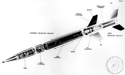
Cut-Away Drawing
This very nifty drawing was taken from the National Air and Space Museum site.